
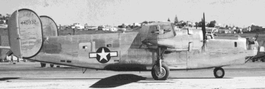
| United States Consolidated B-24 Heavy Bomber B-24J-155-CO-44-40332 |
| |
| |
| |
| |
| |
| |
| |
| |
| |
| |
| B-24 COCKPIT PARTS |
| Stations (Frames) 1.0 through 3.0 - Pilot and Co-Pilot |

| Pilot control wheel assembly with control wheel attached, left photo. Co-Pilot control wheel assembly, missing wheel and internal parts, right photo. |
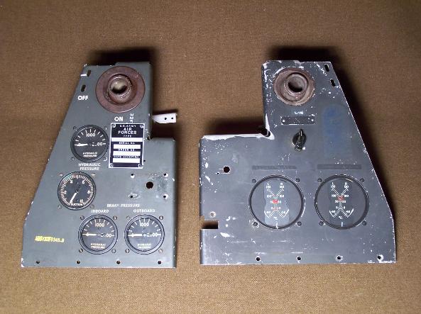

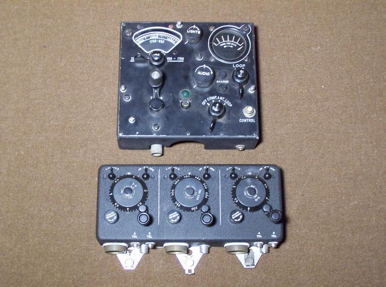
| Pilot (left) and Co-Pilot (right) Auxiliary Instrument Panels, left photo. Pilots Instrument Panel: (3) Type E-4 Hydraulic Pressure Gages, (1) AN-G-24 Suction Gage and Pilot vent. Co-Pilot Instrument Panel: (2) AN-5795-6 Carburetor Gages and Co-Pilot Vent. Right photo, Top Row (L to R): Radio Compass Control Indicator with mount (used only on early B-24's), Turbo Boost Selector, Radio Compass and Mount. Bottom Row (L to R) Engine Switch Panel - Starter and Primer Switches (Co-Pilot side of cockpit), BC-451 Command Radio Control Box (mounted on Pedestal Assembly), Fast Feathering Switch for No. 4 Engine, and switch from Pedestal Mount. |
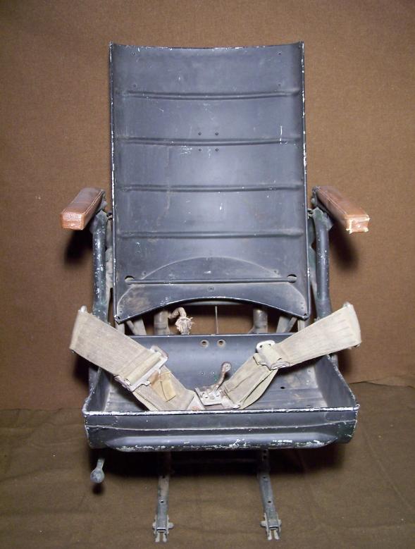
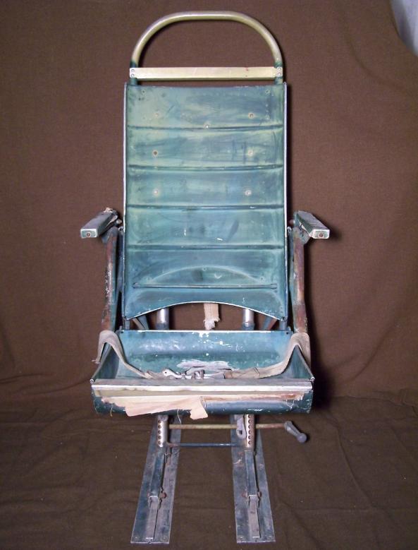
| Pilot Seat, above left photo. Pilot Seat is missing head rest, head rest cushion, back cushion, seat cushion and complete knee pad and support. Co-Pilot Seat, above right photo. Complete with floor track attached. Missing head rest cushion, back rest cushion, seat cushion, arm rest upholstery and knee pad upholstery. |

| Pilot left and right Rudder Pedals with cockpit floor, left photo. Co-Pilot right Rudder Pedal with cockpit floor, right photo. |
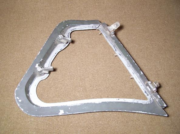
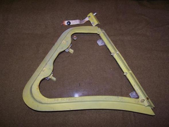
| Pilot cockpit enclosure vent window, missing plexiglass, left photo. Shown from inside of window. Co-Pilot cockpit enclosure vent window, right photo. Shown from outside of window. |
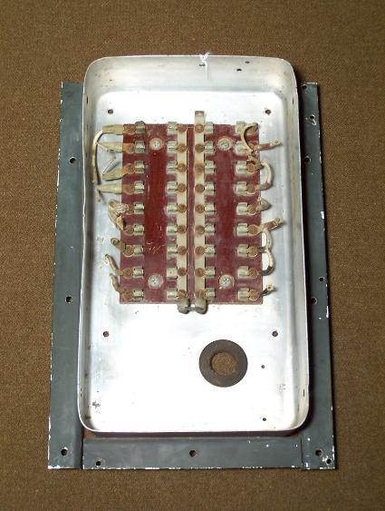
| Co-Pilot fuse box, left photo. Missing fuses and cover. Mounted on Co-Pilot side of fuselage. BC- 434 Radio Control Box (top), BC-450 Radio Control Box (bottom), right photo. Mounted on the cockpit enclosure center frame. |
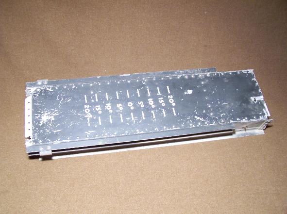

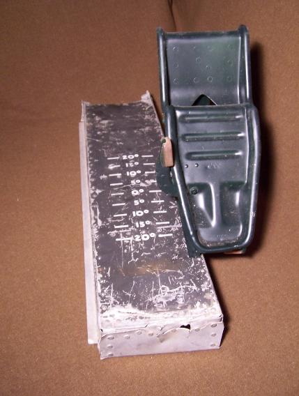
| BC-765 Radio Switchbox, left photo. This box was used to destroy the "special radio" equipment on the B-24 so that it would not be captured by the enemy. Located above the instrument panel below the windscreen. Spare Pilot or Co-Pilot cockpit floor, right photo. Note markings for Rudder Pedal settings. |
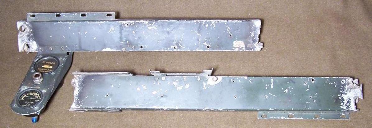
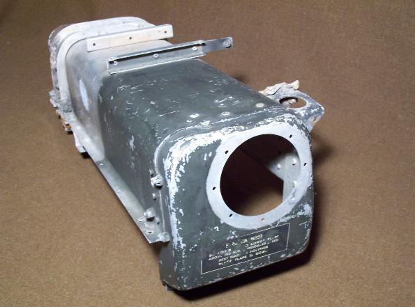
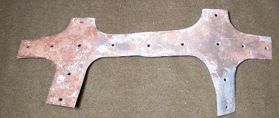
| Instrument panel support assembly, above photo. The support assembly, was the lower part of the instrument panel and allowed the attachment of the Auxiliary Instrument Panels and Control Wheel Assemblies. The above photo shows the pilot section of the support, with oxygen gages attached and the rear of the co-pilot support assembly. |
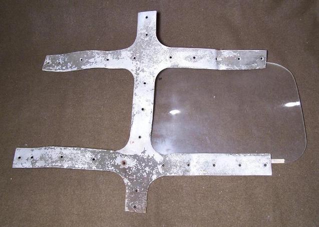
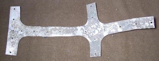
| Cockpit greenhouse sections with one piece of glass, left and both above photos. |
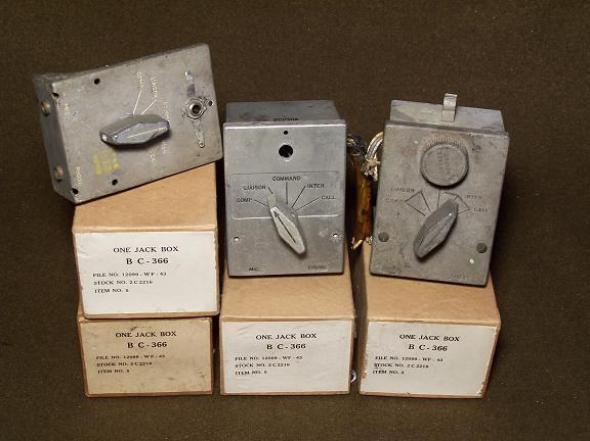
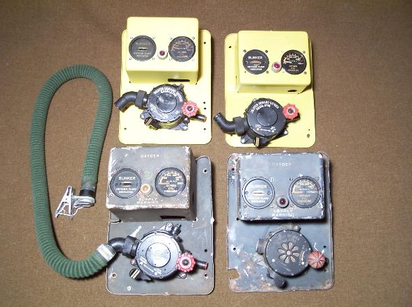
| Four Oxygen Regulator Mounts, above left photo. Each mount contained one Type A-12 or A-12A Oxygen Regulator, AN 6021-1 Oxygen Pressure Gage and AN 6029-1 Oxygen Flow Indicator. One mount was located on either side of the Pilot and Co-Pilot. Seven BC-366 Radio Jack Boxes, above right photo. The BC-366 Jack Box was used to connect the microphone and headset to the radio system. Only two BC-366 Jack Boxes would have been used in the B-24 cockpit. The other five will be used in other areas of the B-24 during this restoration. |
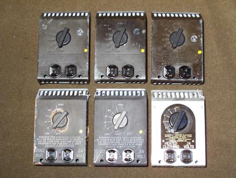
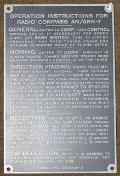
| Six Type Q-1B Heated Flight Suit Rheostat, above left photo. Only two Q-1B's would be used in the cockpit, the other four will be used in other areas of the B-24 during this restoration. Operating Instructions For AN/ARN-7 Radio Plate, above right photo. This plate was located next to the BC-450 Radio Control Box mounted on the cockpit enclosure center frame. |
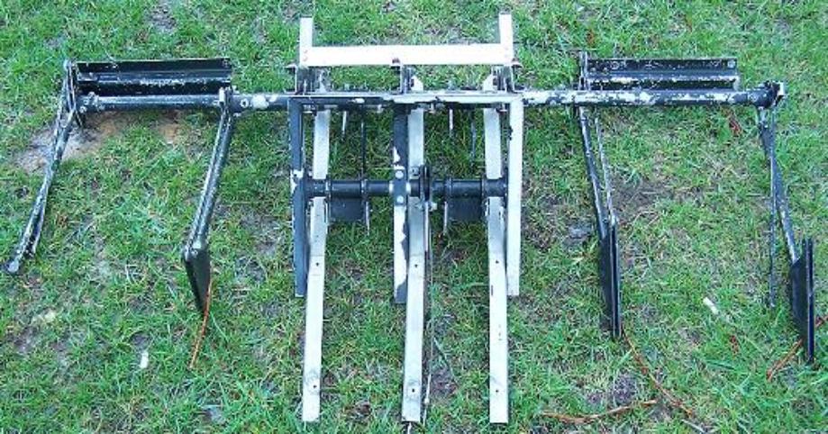
| Rudder pedal control assembly. This is the complete assembly that mounted under the instrument panel. This assembly connected the pilot and co-pilot rudder pedals to the control cables for the rudder. |