
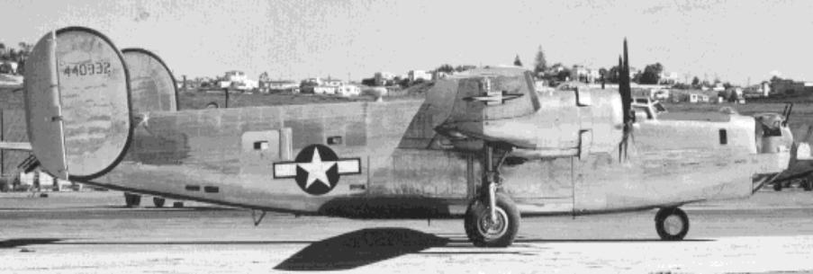
| United States Consolidated B-24 Heavy Bomber B-24J-155-CO-44-40332 |
| |
| |
| |
| |
| |
| |
| |
| |
| |
| |
| B-24 TAIL PARTS |
| Stations (Frames) 6.1 through 10 Ball Turret, Waist Guns and Tail Turret |


| Type E-13 Gun Mount Adapter for left and right waist guns, above two photos. The Type E-13 Adapter held the ANM-2 .50 caliber Machine Gun to the Type K-7 Gun Mount with C-19A Mount Adapter. The E-13 Adapter utilized the Type K-13 Compensating Gun Sight. This configuration was used in late B-24 Liberators that were produced with enclosed waist gun positions. CLICK HERE FOR MORE PICS OF THE WAIST GUNS |


| Waist or Side Gun Ammunition Box, above left and right photo. One ammunition box was provided per gun and contained 600 rounds of .50 caliber ammunition. The white label states: EMERGENCY, TO REMOVE AMMUNITION BOX, PULL HINGE PIN AFT, LIFT EDGE OF BOX AND REMOVE. The ammunition box in the left photo is show with a portion of the feed chute attached. |


| Tail Turret Ammunition Boxes, above left and right photo. These boxes were stacked just aft of the waist gun position and fed the tail turret via a long rigid feed chute. |


| Tail Turret Hydraulic System, left photo. Missing from the system is the Hydraulic Turret Pump Motor. Main Entrance Door Installation, right photo. Mounted in Station 7.4 - 7.6. |


| Hanger and Retraction Cylinder Assembly for the Type A-13 Ball Turret, left photo. Spare Parts Box for A-13 Ball Turret, above top photo. Spare Parts Box, inside view, above right photo. The spare parts box held extra fuses and brushes that may be needed for replacement during flight. |


| Type LP-21 ADF "Football" Radio Antenna, left photo. This antenna was originally black, with stenciling "Do Not Paint". Contrary to instruction, this antenna has been painted silver with unit markings applied. It will be restored, when mated to the fuselage in the original war-time flat-black finish. LP-21 Dehydrator, Loop Antenna, above right photo. The LP-21 Dehydrator was used to draw moisture away from the LP-21 Antenna. The attachment brackets are also shown. |


| Left photo: Inverter Transmitter Assembly Box, Tail Turret Power Switch Box and Inverter Transmitter Assembly Box. The Inverter Transmitter Assembly Box is located under the Radio Operator's floor near Station (Frame) 3.1. Only one Inverter Transmitter Assembly Box was used per aircraft. Right photo: Unknown electrical box cover and unknown fuselage access panel, top row. Fuze Box Cover (Station 4.0), Bomb Release Signal Tail Light Shield and Wing Access Plate, center row. Wing Landing Light Relay Box Assembly Cover, bottom row. |