
| United States Consolidated B-24 Heavy Bomber B-24J-155-CO-44-40332 |

| |
| |
| |
| |
| |
| |
| |
| |
| |
| |
| B-24 BOMB BAY PARTS |
| Stations (Frames) 4.0 through 6.0 - Bomb Bay |
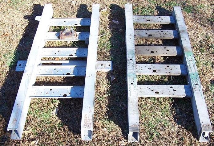
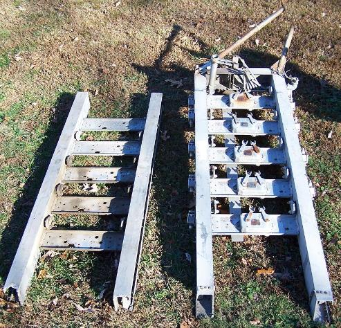
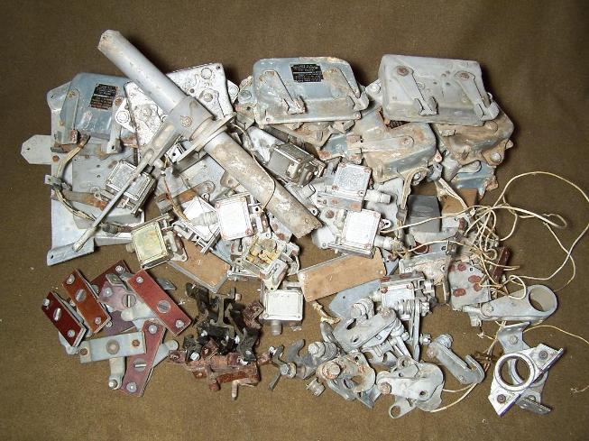
| Bomb racks, above left and right photo. Two racks were located on each side of the bomb bay. |
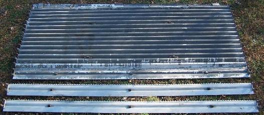
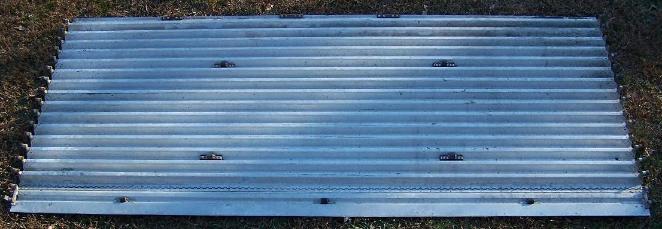
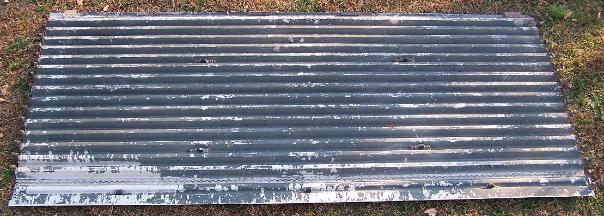
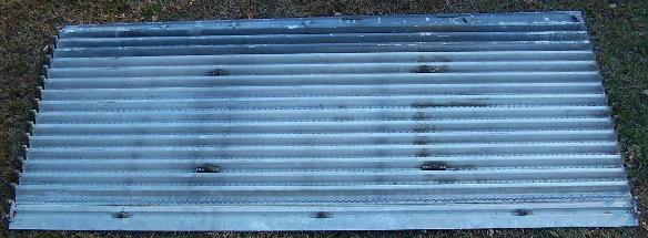
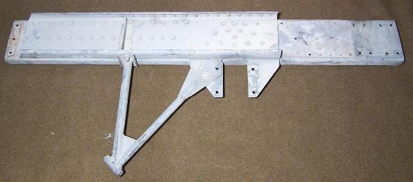
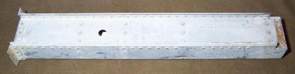
| Bomb Bay Doors, inside view, upper left and right photo and above lower left and right photo. |
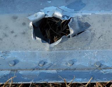
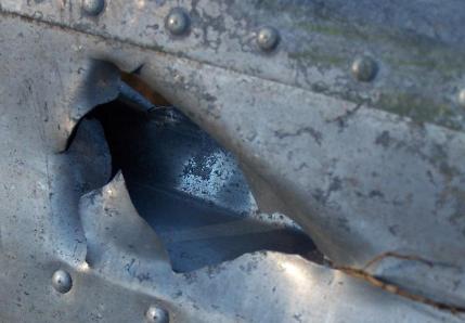
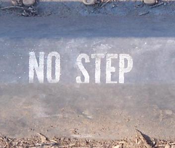
| Bomb Bay Door damage, possibly from wartime anti-aircraft fire, above left and right photo. "NO STEP" decal on bomb bay door, above center photo. |
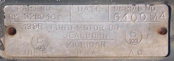
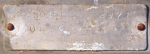
| Bomb Bay Door data plates, left and right photo. Note that the two doors were inspected by two different inspectors. |
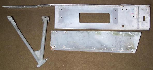
| Bomb Rack supports, upper left, top and right photo). |

| Bomb Rack supports, above left photo. Bomb release control equipment, above right photo. |
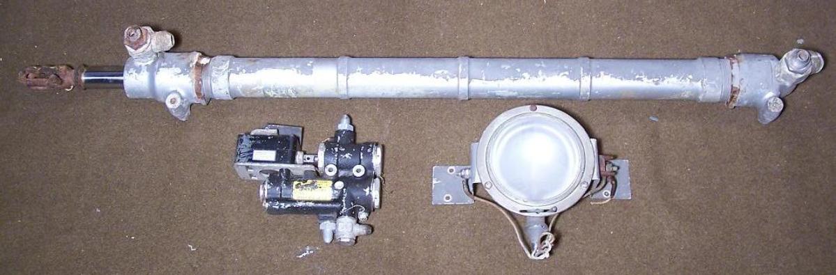
| Bomb Bay Door Hydraulic Assembly, top of photo, Hydraulic Switch, left bottom of photo and Bomb Bay Light, right bottom of photo. |
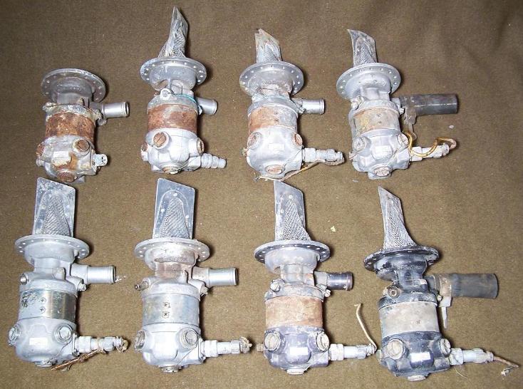
| Fuel Booster Pumps, left photo. Only four fuel booster pumps would be used on one B-24. |
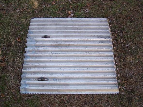
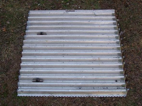
| Bomb Bay Doors, inside view, upper left and right photo. These sections were cut from complete Bomb Bay Doors and are now 3' long. Each section is from the left end of the door. |