
| United States Consolidated B-24 Heavy Bomber B-24J-155-CO-44-40332 |

| |
| |
| |
| |
| |
| |
| |
| |
| |
| |
| B-24 COCKPIT PARTS |
| Stations (Frames) 3.0 through 4.1 - Radio Operator and Top Turret |
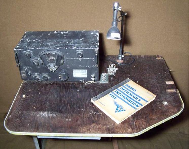
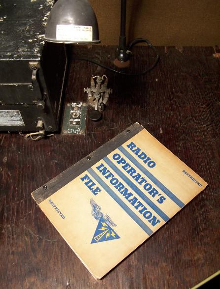
| Radio Operator Table with BC-348 Liaison Radio Receiver, AN-3047 Work Table Light Assembly, J-37 Morse Code Key and Radio Operator's Information File. |
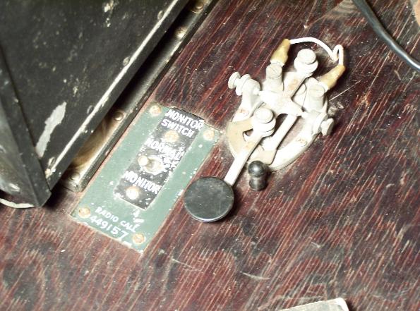

| J-37 Morse Code Key and Monitor Switch, above left photo. Note original "RADIO CALL" number 449157 painted below switch. This Radio Table was removed from Ford B-24L-1-FO-44-49157. BC-348 Liaison Radio Receiver with FT-154 Receiver Mount, above right photo. |

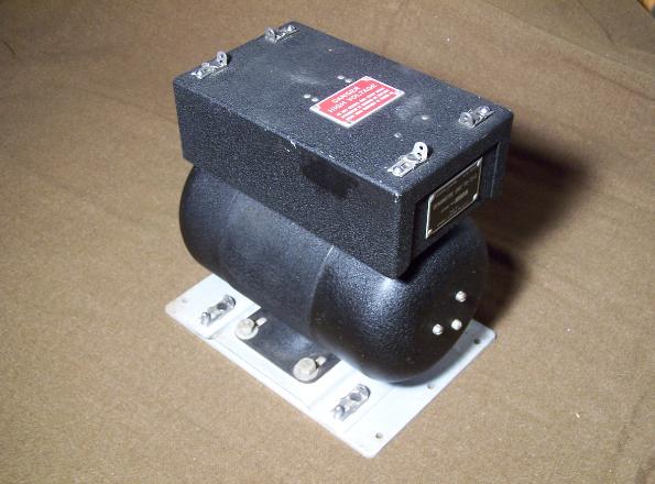
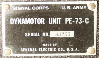
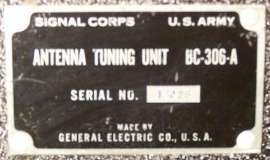
| BC-306 Antenna Tuning Unit with FT-142 Antenna Tuning Unit Mount, left photo. PE-73 Dynamotor Unit with FT-107 Dynamotor Mount, right photo. |
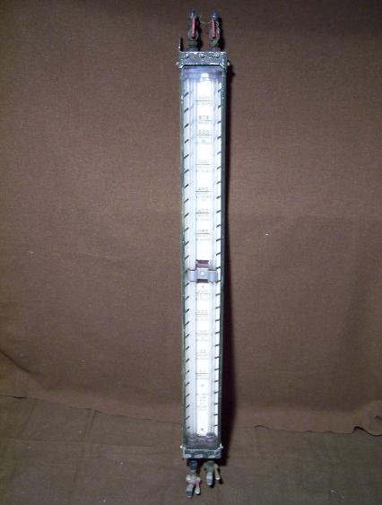
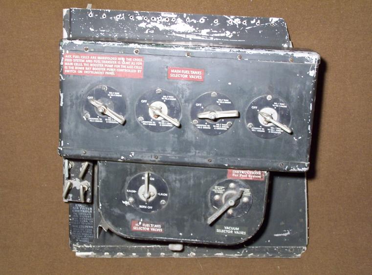
| Fuel Sight Gage, left photo. Main Fuel Tank Selectors Panel, right photo. |
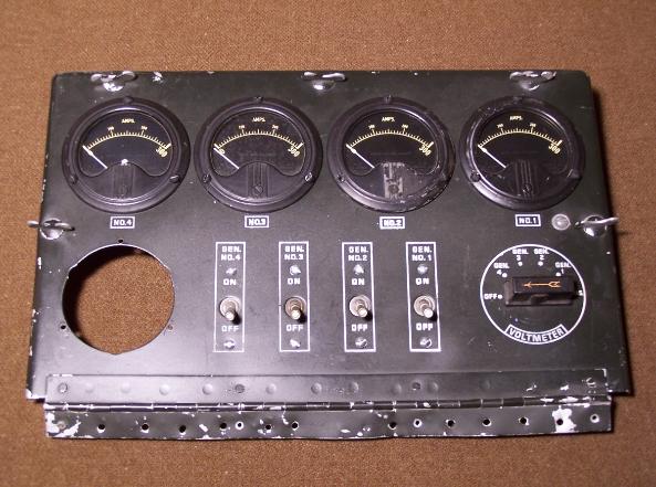
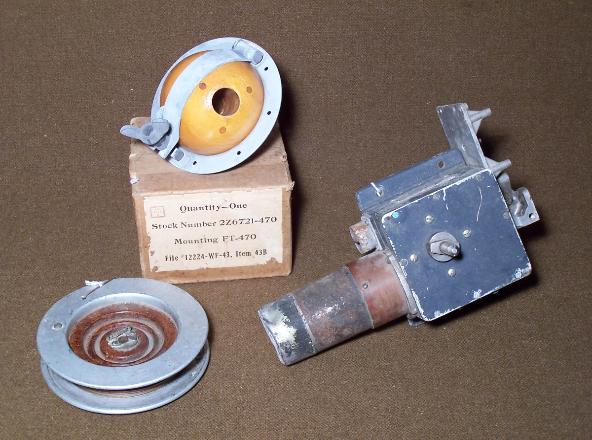
| Power Panel Switch Box Cover with (4) Type E-1 Amperage Gages, above left photo. The panel is missing the Power Switch Box GK32E1043 and Type B-1 Voltmeter. Trailing Antenna, right photo. FT-470 Mounting (Top), M235 Antenna Wire (Left), RL-42 Antenna Reel (Right) |
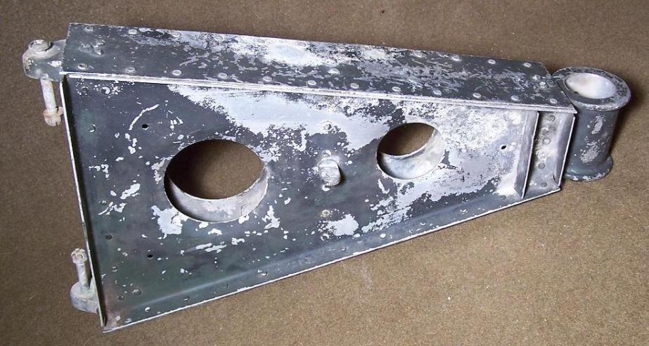
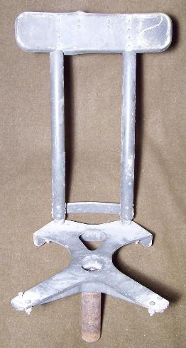
| Radio Operator Seat Support Assembly, above photo. Bombardier's seat assembly, left photo. This style of seat was only used on early B-24's with the "greenhouse" style nose. This seat is very similar to the Radio Operator's seat assembly, and this seat will be used with the support pictured above. |
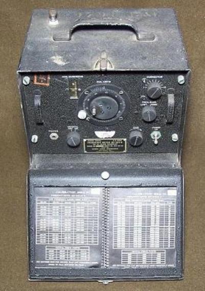
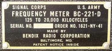
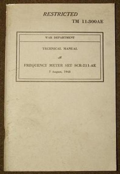
| BC-221 Frequency Meter, left photo. TM 11-300AE BC-211 Manual dated August 7th 1943, right photo. |
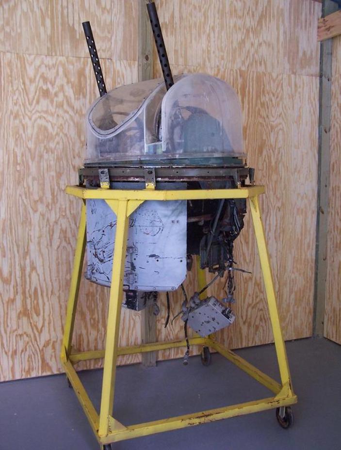
| M-250CE Martin Top Turret, left photo. |